PSPICE SCHEMATICS CAPTURE MANUALS
The CIS option also allows you to transfer component information from a company-owned database.Most of the information contained in these release notes is not included in the PSpice manuals Using the CIS option, circuit diagram symbols and datasheets from online databases can be placed directly in the circuit diagram. OrCAD Capture is also the module for switching inputs from PSpice network lists to simulate analog and mixed-signal circuits.įor designs incorporating programmable devices (such as FPGAs), an Engineering Change Order (ECO) flow is supported, which synchronizes various work steps in the FPGA tool, the circuit diagram, and the PCB Editor by forward and backward annotation. Changes in the logic can be easily imported into the circuit diagram. It also supports a design methodology that integrates the vendor tools of the FPGA manufacturers into the place and route of programmable blocks.


If programmed components are used in the circuit, pin assignments and signals from FPGAs from different manufacturers can be read. In OrCAD Capture assembly variants can be created with several logic functions for a PCB by different bill of materials for each variant. Variants are defined in the schema editor and later output as variants with different parts lists for each variant. In the case of hierarchically structured designs, the same electrical networks are interconnected via cross-porting ports or defined as global networks. The electrical connections (networks) between the associated component pins can be quickly established.

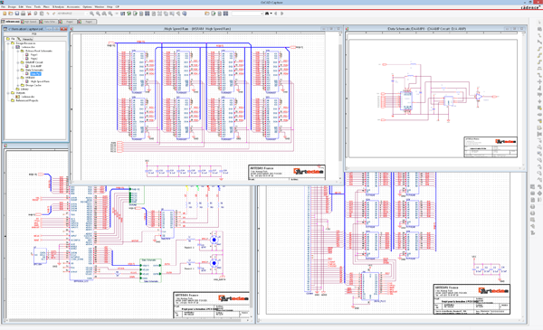
Using the PartBrowser, circuit diagram symbols are selected with the aid of filters from the library and placed in the circuit diagram. Via the navigation window the different pages of the circuit diagram can be selected and thematically managed. OrCAD Capture uses flat or hierarchical circuit diagrams. It is outstanding how simple and intuitive the design intentions are captured.
PSPICE SCHEMATICS CAPTURE SOFTWARE
OrCAD Capture schematic entry tool for circuit diagrams is one of the world's most widely used software for entering and documenting electrical circuits.


 0 kommentar(er)
